When I heard about Libelium’s Arduino Hacking Life contest, I knew it was time for me to finally solve one of my daily annoyances — setting the alarm clock.
Every night, the alarm gets set to a different time. Sometimes there’s an errand in the morning, sometimes an early meeting. On weekends, the alarm usually isn’t needed, unless something’s going on. And then in the morning, I need to set the clock again for my wife’s own set of daily scheduling variables.
Enough! Why should I need to deal with this? Why should I need to stand there pressing buttons time and time again? Why can’t I set my alarm clock with the rest of my schedule — in the calendar? Larmie solves all these problems.
Larmie consists of four components:
- A regular alarm clock, with an interface cable added
- An Arduino with a custom shield, for interfacing with the clock
- A computer, which regularly updates the Arduino with what time to set the alarm to
- A calendar system. Larmie currently uses Google Calendar
 To start, I cracked open my 10+ year old alarm clock. Newer ones might be different, but I’d expect to see essentially the same design in just about every clock. Between the buttons and the LCD is a DIP IC. This looks promising. It’s labeled as LM8560, which a quick Google search tells me is an all-in-one alarm clock. Jackpot.
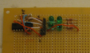
 What I want to do is twiddle the voltage on the LM8560’s input pins, to simulate pressing the buttons on the clock. According to the datasheet, they’re activated at the supply voltage. This is a problem, since the supply voltage is something like 11V, which the Arduino can’t output by itself. To get around this, I used a 7405 hex inverter with open collectors that I had lying around. The hex just means there are 6 inverters (NOT gates) on the chip. The open collector is what’s interesting. When the gate output is logical false, it’s pulled to 0V. When it’s logical true, the pin floats. You can pull it to whatever voltage you need. I pull it to the clock’s high with a resistor, and put in an LED as an indicator. After testing it out a breadboard, I put together the final circuit on some perf board. Here is the schematic.

The Arduino expects to be told the alarm over a serial connection. This can actually be over USB, XBee, Ethernet, or whatever is convenient. I followed the datasheet for how to set and reset the alarm and time. The datasheet doesn’t describe how quickly you can pulse the inputs, but I found that 25 ms and 25 ms off works reliably, and still fast enough to set the time in a few seconds. The biggest challenge in writing the Larmie firmware was avoiding setting off the alarm while setting it. If the current time and alarm time are ever the same, the alarm will continue to go. On top of that, I can’t read the current time out of the clock. Instead, I have the current time sent along with the alarm time. Since there might be a minute or two difference between the clock and the time on the PC, I’ll need to avoid a whole range. That gets complicated around the beginning and end of an hour, so the firmware simply refuses to set the alarm at those times. Since the PC component should be running every few minutes, this doesn’t matter very much.
The last piece is a small Python script that requests event data from Google Calendar, and sends the alarm time to the Arduino. This script should be run periodically, using something like launchd on OS X, cron on Linux, or Scheduled Tasks on Windows. The interface between the PC and the Arduino is very simple, so this component can be swapped out for whatever’s convenient.
Download the source, including circuit diagram, Arduino code, and Python.
Source code for Larmie