While developing the software to use the XBee Roomba adapter I previously described, I discovered the Roomba was spewing data.
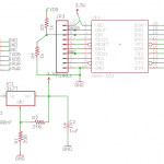
My first guess was a bad solder joint, specifically the wire soldered to the mini-DIN connector. If that went open, the voltage divider would pull the data input to the XBee to ground. That joint wasn’t particularly great to begin with, and got pushed around when finishing assembly and using the board.. Unfortunately, I had covered the mini-DIN solder joints in hot glue in an attempt to prevent physical stress, so I couldn’t just heat up the joint and toss on a bit more solder. I replaced the connector with a spare, but the problem was still there. That’s when I noticed that the amount of bad data didn’t seem to be change when poking at the board and wires, so it probably wasn’t a physical problem. I measured the voltage on the data input pin, and discovered it was only about 1.6V. That puts it in the undefined area of whether the XBee will consider it high or low. So I found the problem. Different families of logic devices have different ranges of voltages that it will consider high or low, or output as high or low. Unfortunately, the Roomba doesn’t document it’s thresholds, just that it’s a 5V device. It turns out mine seems to output at about 3.4V, at least under the conditions I tested it. I clipped off the bottom half of the voltage divider (R4), leaving a 1 kΩ resistor between the Roomba’s output and the XBee’s input, and the noise went away. So it works, but is it safe? In short, no. But there isn’t enough documentation to design a safe divider. The XBee doesn’t give a maximum safe voltage, but the EM250 that it’s based on says Vcc + 0.3V. I’m supplying 3.3V to the XBee, so that means up to 3.6V. The Roomba doesn’t document it’s maximum output. If I divide enough to keep safe at 5V input, it wouldn’t work at the measured 3.4V. For now, I’m living dangerously. The remaining resistor (R3) should protect against high current, which tends to be more damaging. If I damage the XBee, I’ll have to design a new board. And then come up with a use for an XBee without a working serial input.Category Archives: roomba
XBee adapter for Roomba
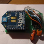
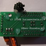
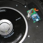
A few months ago, I decided on Digi’s XBee modules for my wireless projects. Today I’m showing off the first completed project — a wireless Roomba adapter. This project represents a number of firsts for me.
- First semi-practical use of XBee
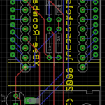
- First time designing a PCB, using Eagle
- First custom PCB order, from BatchPCB
