Category Archives: xbee

Quasar, yet another DIY ambient orb (with wireless!)

This project has been done many times, so I won’t go into much detail. I wanted a general purpose notifier, especially once I built Laundrymon. I figured a box with a high powered RGB LED and an XBee would fit the bill. The enclosure is just a project box with a sheet of cheap copy paper shaped with some wire and hot glue. I added a photoresistor to dim the light in the bedroom at night.

I’m building a couple of these to scatter throughout the house so I always know when the laundry’s done, an email arrives, or whatever else I might want to be notified about.

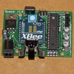
Important note: I misplaced one of the capacitors when designing the board. It seems to be running well enough with a wire in its place. It’s the one on the right in the lower left corner, above the power connector.

Downloads the source and Eagle files
Buy the PCB from BatchPCB

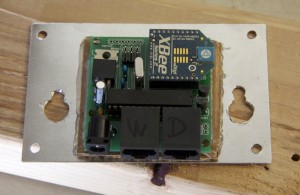
Quasar in actionQuasar populated board

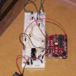
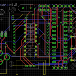
Quasar breadboard prototypeQuasar PCB design

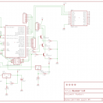
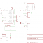
Quasar schematic

Laundrymon, the wireless, noninvasive, Arduino-based, laundry monitor

Laundrymon populated circuit board
I always forget to set a timer when doing laundry, and the machines are in the garage so they’re hard to hear. I’ve seen a couple of approaches to remotely monitor laundry machines. Unfortunately, I am not a commerical laundromat, and the since machines belong to the landlady I can’t really open them up to hack on. I needed a non-invasive solution.

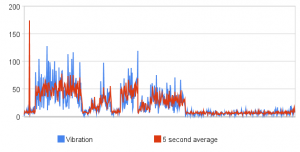
The ideal approach would be something that I could put next to the washer and dryer that would passively detect whether the machine was running. Laundry machines generally vibrate pretty much, so I decided to try to use an accelerometer to detect vibration. The Wii Nunchuk is a handy accelerometer with an I2C interface with Arduino code available. So I bought an adapter, wrote a basic logging sketch, and taped a Nunchuk to the side of the washer to see what would happen.

Laundrymon graph

Hey, looks like this might actually work!

It turns out that even if you pay the full retail price of $20, the Nunchuk is still pretty much the cheapest accelerometer you can buy once it’s broken out from a tiny surface mount package. I needed two Nunchuks — one for the washer and one for the dryer. Normally, it’s easy to have multiple I2C devices connected together, but the Nunchuk has the slave address hard coded. That’s easily solved with a few transistors.

Time to put it all together. While the Nunchuk adapters are great for prototyping, they don’t really give a solid connection, so I swapped the cable for some network cable I had lying around. I started with a basic breadboard Arduino tutorial, and added an XBee for wireless and the nunchuk circuitry. I used the excellent BatchPCB for fabrication. Even though the final board doesn’t looks much like an Arduino, it’s based on at Atmega168, so I can still use the Arduino IDE to develop the firmware.

Right now, all it does it play a sound on my home theater PC. My next project is to make a bunch of blinkie notifiers to scatter throughout the house.

Download the source and Eagle files
Buy the PCB from BatchPCB

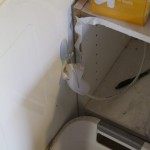
Full Laundrymon setupNunchuk hang off of the dryer

Laundrymon schematicLaundrymon circuitboard design

XBee Roomba problems

While developing the software to use the XBee Roomba adapter I previously described, I discovered the Roomba was spewing data.

My first guess was a bad solder joint, specifically the wire soldered to the mini-DIN connector. If that went open, the voltage divider would pull the data input to the XBee to ground. That joint wasn’t particularly great to begin with, and got pushed around when finishing assembly and using the board.. Unfortunately, I had covered the mini-DIN solder joints in hot glue in an attempt to prevent physical stress, so I couldn’t just heat up the joint and toss on a bit more solder. I replaced the connector with a spare, but the problem was still there.

That’s when I noticed that the amount of bad data didn’t seem to be change when poking at the board and wires, so it probably wasn’t a physical problem. I measured the voltage on the data input pin, and discovered it was only about 1.6V. That puts it in the undefined area of whether the XBee will consider it high or low. So I found the problem.

Different families of logic devices have different ranges of voltages that it will consider high or low, or output as high or low. Unfortunately, the Roomba doesn’t document it’s thresholds, just that it’s a 5V device. It turns out mine seems to output at about 3.4V, at least under the conditions I tested it.

I clipped off the bottom half of the voltage divider (R4), leaving a 1 kΩ resistor between the Roomba’s output and the XBee’s input, and the noise went away. So it works, but is it safe?

In short, no. But there isn’t enough documentation to design a safe divider. The XBee doesn’t give a maximum safe voltage, but the EM250 that it’s based on says Vcc + 0.3V. I’m supplying 3.3V to the XBee, so that means up to 3.6V. The Roomba doesn’t document it’s maximum output. If I divide enough to keep safe at 5V input, it wouldn’t work at the measured 3.4V.

For now, I’m living dangerously. The remaining resistor (R3) should protect against high current, which tends to be more damaging. If I damage the XBee, I’ll have to design a new board. And then come up with a use for an XBee without a working serial input.